
While our last focus was on the IV-11 VFD tube - since we had to design a circuit that make the tubes glow and display the stuff we want it to, now the microcontroller is in the spotlight for adding fundamental features, such as a real time clock to the circuit.
The second part of the article is meant to be read in a flow since every step would require its own testing code.
At the end however, you can put it all together on breadboard or any real PCB.
And we're ready to upload the latest OpenVFD firmware to our completed circuit and enjoy how far we've come!
STEP 1: MEET THE MICROCONTROLLER

OpenVFD could've been powered by this hipster microcontroller on the left picture. What you see is an old school Intel® MCS-51 (8051)microcontroller in a nobel golden ceramic DIP package.
The choice fell on the Atmel® ATmega328P though, because Arduino® Uno shares exactly the same powerful processor. We begin by designing a fundamental circuit that makes developing on OpenVFD feel like working with the regular Uno environment. Just like reverse-engineering you first analyze the Uno schematics and take it apart. Then it's time to remove all the stuff that's not necessary for basic functionality and put it back together again with its essentials. Let's go!
Do you know what we will need for basic functionality?
We need a supply voltage of 5V. This is done by connecting the VCC pin to 5V and GND pins to ground. Also, AVCC gets the same 5V connection
Like every processor, we need a clock frequency. While the AVR® has a built in, internal oscillator, we - just like the Uno - use an external one for maximum performance. The corresponding circuit is connected to pin 9 and 10 of the processor
Everything can be solved by a reboot. Right? Exactly, so we could also use some emergency circuitry which helps to reset the µC. That's everything connected to pin 1. Don't mind that capacitor to DTR (C10). We'll talk about that later.
STEP 2: COMPLETING THE UNO

We complete the Uno compatible circuit by adding the status LEDs on serial transfer pins RxD, TxD and pin 13. One more LED indicates, that our circuit is powered on.
Like the original Uno, the serial LEDs RxD and TxD turn on when the pin is LOW. Conversely, pin 13 will turn on when the output is 5V.

Thinking about makes developing on the Arduino® platform super convenient I found and believe it's the simplicity of uploading code to the microcontroller using just a USB cable! Developing on OpenVFD should be as intuitive it is on an Arduino® Uno.
So we found the Chinese WCH CH340G as a reliable and easy to use communicator between the computer and OpenVFD. DTR will make OpenVFD reboot automatically when being connected to a computer.
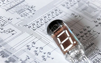
STEP 3: THE REAL TIME CLOCK - DS1307 VS DS3231
What else do we need for the VFD clock? Oh right... it's the clock. So finally we're adding a circuit that provides clock functionality. Our so called RTC (real time clock) is backed up with a battery so that the clock can tick on even if OpenVFD is turned off itself. That makes sense, right? Since we wouldn't want to set the time everytime we power on. We choose between a DS1307 and a DS3231 module:
The DS1307 is an affordable RTC solution, simple to control but with trade-off in accuracy depending on the crystal used - which is in general pretty inaccurate due to temperature change. I had situations where the DS1307 was a minute or more off after a day. That wouldn't work in a commercial product at all
Luckily, the DS1307 module can easily be drop-in replaced by a DS3231 module. The DS3231 is a RTC with a TCXO (temperature compensated crystal oscillator) ensuring jaw-dropping accuracy of less than a minute error per year
After all it depends on your expectation of accuracy, which module you want to use for your VFD clock. Both are tested to be both pin and source code compatible to the OpenVFD schematics and firmware (software).
STEP 4: LIGHT UP THE CLOCK


Ready? Shop soldering kits and pre-built VFD clocks with RGB + warm white backlights at my Etsy store. Ships from Switzerland to everywhere.
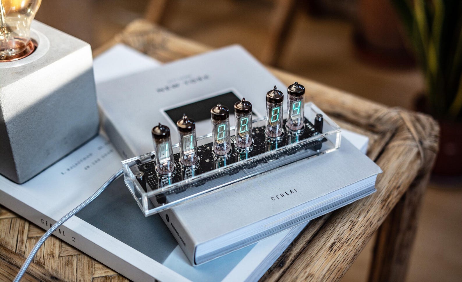
Visit my Etsy Store →Now let's add the most memorable characteristic of the OpenVFD clock: The LEDs that light up the tubes to create the effects and moods that we all love. It begins by finding the right RGB LED that is reliable and bright. Why RGB? Here's how beautiful colors work: We combine the three colors of RGB (red, green and blue) to get new colors. So for instance purple is just blue and red mixed together.
Meet the WS2812B digital LED. This LED acts like a shift register and is controlled by shuttling data through one single data pin.
What makes the WS2812B really lovely is that the exact same LED is found in NeoPixel by Adafruit®. Even though the OpenVFD firmware does not rely on any Adafruit® libraries, Adafruit® still provide brilliant documentation on this LED that help when working with them. Take a look at the connection diagram. OpenVFD chained up six WS2812Bs to light up the six tubes individually.
STEP 5: EVERYTHING ELSE
For the time OpenVFD is not connected to a PC, four push buttons are used to set time, play with colors and do much more. The firmware OpenVFD makes them reacting to short and long presses.
A microphone module (MAX9812) makes your VFD clock dance to the tunes you enjoy. It measures sound as variations in air pressure and sends corresponding electric signals that are then evaluated by the microcontroller. Temperature measurement is done by a LM35 sensor that converts temperature into voltage levels. Our microcontroller translates this back to a temperature value that we all understand.
STEP 7: PUTTING IT ALL TOGETHER

And we're done with the complete VFD clock circuit design. You can download the complete prototyping circuit diagram on the right. If you got it on breadboard or prototype board by now, we're totally ready to upload the OpenVFD firmware to your microcontroller.
Prototyping Circuit Diagram
File Format: PNG Graphic, 223 KB
Here's the OpenVFD Firmware in its latest version. When compiling on your own, make sure the libraries RTClib, Wire and digitalWriteFast are ready. These are the only dependencies of OpenVFD. In the present circuit configuration, you can also upload the firmware using myOpenVFD (the PC tool that can control OpenVFD). The only requirement is the Arduino® Uno bootloader installed on the AVR microcontroller. Otherwise, use the Firmware .HEX file to upload the latest firmware to the AVR® microcontroller directly using SPI or HV programming.
Latest OpenVFD: 6-Digit IV-11 VFD Clock Firmware C/C++ Code:
1 2 3 4 5 6 7 8 9 10 11 12 13 14 15 16 17 18 19 20 21 22 23 24 25 26 27 28 29 30 31 32 33 34 35 36 37 38 39 40 41 42 43 44 45 46 47 48 49 50 51 52 53 54 55 56 57 58 59 60 61 62 63 64 65 66 67 68 69 70 71 72 73 74 75 76 77 78 79 80 81 82 83 84 85 86 87 88 89 90 91 92 93 94 95 96 97 98 99 100 101 102 103 104 105 106 107 108 109 110 111 112 113 114 115 116 117 118 119 120 121 122 123 124 125 126 127 128 129 130 131 132 133 134 135 136 137 138 139 140 141 142 143 144 145 146 147 148 149 150 151 152 153 154 155 156 157 158 159 160 161 162 163 164 165 166 167 168 169 170 171 172 173 174 175 176 177 178 179 180 181 182 183 184 185 186 187 188 189 190 191 192 193 194 195 196 197 198 199 200 201 202 203 204 205 206 207 208 209 210 211 212 213 214 215 216 217 218 219 220 221 222 223 224 225 226 227 228 229 230 231 232 233 234 235 236 237 238 239 240 241 242 243 244 245 246 247 248 249 250 251 252 253 254 255 256 257 258 259 260 261 262 263 264 265 266 267 268 269 270 271 272 273 274 275 276 277 278 279 280 281 282 283 284 285 286 287 288 289 290 291 292 293 294 295 296 297 298 299 300 301 302 303 304 305 306 307 308 309 310 311 312 313 314 315 316 317 318 319 320 321 322 323 324 325 326 327 328 329 330 331 332 333 334 335 336 337 338 339 340 341 342 343 344 345 346 347 348 349 350 351 352 353 354 355 356 357 358 359 360 361 362 363 364 365 366 367 368 369 370 371 372 373 374 375 376 377 378 379 380 381 382 383 384 385 386 387 388 389 390 391 392 393 394 395 396 397 398 399 400 401 402 403 404 405 406 407 408 409 410 411 412 413 414 415 416 417 418 419 420 421 422 423 424 425 426 427 428 429 430 431 432 433 434 435 436 437 438 439 440 441 442 443 444 445 446 447 448 449 450 451 452 453 454 455 456 457 458 459 460 461 462 463 464 465 466 467 468 469 470 471 472 473 474 475 476 477 478 479 480 481 482 483 484 485 486 487 488 489 490 491 492 493 494 495 496 497 498 499 500 501 502 503 504 505 506 507 508 509 510 511 512 513 514 515 516 517 518 519 520 521 522 523 524 525 526 527 528 529 530 531 532 533 534 535 536 537 538 539 540 541 542 543 544 545 546 547 548 549 550 551 552 553 554 555 556 557 558 559 560 561 562 563 564 565 566 567 568 569 570 571 572 573 574 575 576 577 578 579 580 581 582 583 584 585 586 587 588 589 590 591 592 593 594 595 596 597 598 599 600 601 602 603 604 605 606 607 608 609 610 611 612 613 614 615 616 617 618 619 620 621 622 623 624 625 626 627 628 629 630 631 632 633 634 635 636 637 638 639 640 641 642 643 644 645 646 647 648 649 650 651 652 653 654 655 656 657 658 659 660 661 662 663 664 665 666 667 668 669 670 671 672 673 674 675 676 677 678 679 680 681 682 683 684 685 686 687 688 689 690 691 692 693 694 695 696 697 698 699 700 701 702 703 704 705 706 707 708 709 710 711 712 713 714 715 716 717 718 719 720 721 722 723 724 725 726 727 728 729 730 731 732 733 734 735 736 737 738 739 740 741 742 743 744 745 746 747 748 749 750 751 752 753 754 755 756 757 758 759 760 761 762 763 764 765 766 767 768 769 770 771 772 773 774 775 776 777 778 779 780 781 782 783 784 785 786 787 788 789 790 791 792 793 794 795 796 797 798 799 800 801 802 803 804 805 806 807 808 809 810 811 812 813 814 815 816 817 818 819 820 821 822 823 824 825 826 827 828 829 830 831 832 833 834 835 836 837 838 839 840 841 842 843 844 845 846 847 848 849 850 851 852 853 854 855 856 857 858 859 860 861 862 863 864 865 866 867 868 869 870 871 872 873 874 875 876 877 878 879 880 881 882 883 884 885 886 887 888 889 890 891 892 893 894 895 896 897 898 899 900 901 902 903 904 905 906 907 908 909 910 911 912 913 914 915 916 917 918 919 920 921 922 923 924 925 926 927 928 929 930 931 932 933 934 935 936 937 938 939 940 941 942 943 944 945 946 947 948 949 950 951 952 953 954 955 956 957 958 959 960 961 962 963 964 965 966 967 968 969 970 971 972 973 974 975 976 977 978 979 980 981 982 983 984 985 986 987 988 989 990 991 992 993 994 995 996 997 998 999 1000 1001 1002 1003 1004 1005 1006 1007 1008 1009 1010 1011 1012 1013 1014 1015 1016 1017 1018 1019 1020 1021 1022 1023 1024 1025 1026 1027 1028 1029 1030 1031 1032 1033 1034 1035 1036 1037 1038 1039 1040 1041 1042 1043 1044 1045 1046 1047 1048 1049 1050 1051 1052 1053 1054 1055 1056 1057 1058 1059 1060 1061 1062 1063 1064 1065 1066 1067 1068 1069 1070 1071 1072 1073 1074 1075 1076 1077 1078 1079 1080 1081 1082 1083 1084 1085 1086 1087 1088 1089 1090 1091 1092 1093 1094 1095 1096 1097 1098 1099 1100 1101 1102 1103 1104 1105 1106 1107 1108 1109 1110 1111 1112 1113 1114 1115 1116 1117 1118 1119 1120 1121 1122 1123 1124 1125 1126 1127 1128 1129 1130 1131 1132 1133 1134 1135 1136 1137 1138 1139 1140 1141 1142 1143 1144 1145 1146 1147 1148 1149 1150 1151 1152 1153 1154 1155 1156 1157 1158 1159 1160 1161 1162 1163 1164 1165 1166 1167 1168 1169 1170 1171 1172 1173 1174 1175 1176 1177 1178 1179 1180 1181 1182 1183 1184 1185 1186 1187 1188 1189 1190 1191 1192 1193 1194 1195 1196 1197 1198 1199 1200 1201 1202 1203 1204 1205 1206 1207 1208 1209 1210 1211 1212 1213 1214 1215 1216 1217 1218 1219 1220 1221 1222 1223 1224 1225 1226 1227 1228 1229 1230 1231 1232 1233 1234 1235 1236 1237 1238 1239 1240 1241 1242 1243 1244 1245 1246 1247 1248 1249 1250 1251 1252 1253 1254 1255 1256 1257 1258 1259 1260 1261 1262 1263 1264 1265 1266 1267 1268 1269 1270 1271 1272 1273 1274 1275 1276 1277 1278 1279 1280 1281 1282 1283 1284 1285 1286 1287 1288 1289 1290 1291 1292 1293 1294 1295 1296 1297 1298 1299 1300 1301 1302 1303 1304 1305 1306 1307 1308 1309 1310 1311 1312 1313 1314 1315 1316 1317 1318 1319 1320 1321 1322 1323 1324 1325 1326 1327 1328 1329 1330 1331 1332 1333 1334 1335 1336 1337 1338 1339 1340 1341 1342 1343 1344 1345 1346 1347 1348 1349 1350 1351 1352 1353 1354 1355 1356 1357 1358 1359 1360 1361 1362 1363 1364 1365 1366 1367 1368 1369 1370 1371 1372 1373 1374 1375 1376 1377 1378 1379 1380 1381 1382 1383 1384 1385 1386 1387 1388 1389 1390 1391 1392 1393 1394 1395 1396 1397 1398 1399 1400 1401 1402 1403 1404 1405 1406 1407 1408 1409 1410 1411 1412 1413 1414 1415 1416 1417 1418 1419 1420 1421 1422 1423 1424 1425 1426 1427 1428 1429 1430 1431 1432 1433 1434 1435 1436 1437 1438 1439 1440 1441 1442 1443 1444 1445 1446 1447 1448 1449 1450 1451 1452 1453 1454 1455 1456 1457 1458 1459 1460 1461 1462 1463 1464 1465 1466 1467 1468 1469 1470 1471 1472 1473 1474 1475 1476 1477 1478 1479 1480 1481 1482 1483 1484 1485 1486 1487 1488 1489 1490 1491 1492 1493 1494 1495 1496 1497 1498 1499 1500 1501 1502 1503 1504 1505 1506 1507 1508 1509 1510 1511 1512 1513 1514 1515 1516 1517 1518 1519 1520 1521 1522 1523 1524 1525 1526 1527 1528 1529 1530 1531 1532 1533 1534 1535 1536 1537 1538 1539 1540 1541 1542 1543 1544 1545 1546 1547 1548 1549 1550 1551 1552 1553 1554 1555 1556 1557 1558 1559 1560 1561 1562 1563 1564 1565 1566 1567 1568 1569 1570 1571 1572 1573 1574 1575 1576 1577 1578 1579 1580 1581 1582 1583 1584 1585 1586 1587 1588 1589 1590 1591 1592 1593 1594 1595 1596 1597 1598 1599 1600 1601 1602 1603 1604 1605 1606 1607 1608 1609 1610 1611 1612 1613 1614 1615 1616 1617 1618 1619 1620 1621 1622 1623 1624 1625 1626 1627 1628 1629 1630 1631 1632 1633 1634 1635 1636 1637 1638 1639 1640 1641 1642 1643 1644 1645 1646 1647 1648 1649 1650 1651 1652 1653 1654 1655 1656 1657 1658 1659 1660 1661 1662 1663 1664 1665 1666 1667 1668 1669 1670 1671 1672 1673 1674 1675 1676 1677 1678 1679 1680 1681 1682 1683 1684 1685 1686 1687 1688 1689 1690 1691 1692 1693 1694 1695 1696 1697 1698 1699 1700 1701 1702 1703 1704 1705 1706 1707 1708 1709 1710 1711 1712 1713 1714 1715 1716 1717 1718 1719 1720 1721 1722 1723 1724 1725 1726 1727 1728 1729 1730 1731 1732 1733 1734 1735 1736 1737 1738 1739 1740 1741 1742 1743 1744 1745 1746 1747 1748 1749 1750 1751 1752 1753 1754 1755 1756 1757 1758 1759 1760 1761 1762 1763 1764 1765 1766 1767 1768 1769 1770 1771 1772 1773 1774 1775 1776 1777 1778 1779 1780 1781 1782 1783 1784 1785 1786 1787 1788 1789 1790 1791 1792 1793 1794 1795 1796 1797 1798 1799 1800 1801 1802 1803 1804 1805 1806 1807 1808 1809 1810 1811 1812 1813 1814 1815 1816 1817 1818 1819 1820 1821 1822 1823 1824 1825 1826 1827 1828 1829 1830 1831 |
/*MIT License Copyright (c) 2017 Frank F. Zheng, Date: 07/06/2017, 06:12 PM Permission is hereby granted, free of charge, to any person obtaining a copy of this software and associated documentation files (the "Software"), to deal in the Software without restriction, including without limitation the rights to use, copy, modify, merge, publish, distribute, sublicense, and/or sell copies of the Software, and to permit persons to whom the Software is furnished to do so, subject to the following conditions: The above copyright notice and this permission notice shall be included in all copies or substantial portions of the Software. THE SOFTWARE IS PROVIDED "AS IS", WITHOUT WARRANTY OF ANY KIND, EXPRESS OR IMPLIED, INCLUDING BUT NOT LIMITED TO THE WARRANTIES OF MERCHANTABILITY, FITNESS FOR A PARTICULAR PURPOSE AND NONINFRINGEMENT. IN NO EVENT SHALL THE AUTHORS OR COPYRIGHT HOLDERS BE LIABLE FOR ANY CLAIM, DAMAGES OR OTHER LIABILITY, WHETHER IN AN ACTION OF CONTRACT, TORT OR OTHERWISE, ARISING FROM, OUT OF OR IN CONNECTION WITH THE SOFTWARE OR THE USE OR OTHER DEALINGS IN THE SOFTWARE.*/ // --------- Includes --------- #include <RTClib.h> // RTC Clock Library #include <Wire.h> // RTC Clock Communication Library (Wire) #include <digitalWriteFast.h> // Clock Cycle Optimized Output #include <EEPROM.h> // EEPROM Access // --------- Pin Mapping Defines --------- // Pin Name | A | ATMEGA Mapping | Comment, Schematics Signal Name // ------------------------------------------------------------------------------------------ #define CLOCK_PIN 2 // ATMEGA: 4 74HC595 SPI Clock Pin, SCK #define LATCH_PIN 3 // ATMEGA: 5 74HC595 SPI Latch Pin, RCK #define DATA_PIN 4 // ATMEGA: 6 74HC595 SPI Data Pin, SER #define B_TEN_PIN 5 // ATMEGA: 11 Time Enable Button Input Pin, B_TEN #define B_CHY_PIN 6 // ATMEGA: 12 Color Set / Hour / Year Button Input Pin, B_CHY #define B_VMM_PIN 7 // ATMEGA: 13 VU Sensitivity / Minute / Month Button Input Pin, B_VMM #define B_MSD_PIN 8 // ATMEGA: 14 Clock Mode / Second / Day Button Input Pin, B_MSD #define LED_PIN 13 // ATMEGA: 19 LED Pin, LEDPIN #define MIC_PIN A0 // ATMEGA: 23 Microphone Input Pin, MIN #define STEM_PIN A1 // ATMEGA: 24 Temperature Sensor Input Pin, STEM // ------------------------------------------------------------------------------------------ #define SHORTPRESS 1 // Short press is 1 #define LONGPRESS 2 // Long press is 2 #define NUM_RGB 6 // 6 LEDs for OpenVFD #define NUM_BYTES (NUM_RGB * 3) // 3 * 6 = 18 bytes #define PORT (PORTB) // Digital pin's port #define PORT_PIN (PORTB5) // Digital pin's bit position #define NUM_BITS (8) // Const 8 // Used for LED crossfade phase value #define PI85 0.0369599135716446263348546280 #define DS3231 // FIRMWARE VERSION STRING // Version 2.01 final, Date: 07/06/2017, 06:12 PM char fwString[7] = {'v', '2', '.', '0', '1', ' ', ' '}; // --------- Component Initializer --------- RTC_DS1307 rtc; // --------- Global Variable Initializer --------- uint8_t interface = 0; // Global Display Mode uint8_t led = 0; // Global LED Mode char welcomeText[6] = {'H', 'E', 'L', 'L', 'O', ' '}; uint8_t tsmCounter = 0; // Temperature Sensor Measurement Amount Counter uint32_t tsmValues = 0; // Temperature sensor measurement storage uint32_t ts; // Mean temperature value uint8_t isFahrenheit = 0; // Fahrenheit flag uint8_t INTF0_DM = 0; // Interface 0 dot mode counter uint8_t INTF0_DP = 0; // Interface 0 dot position uint8_t INTF0_ds = 0; // Interface 0 dot mode: second flip time delta flag boolean INTF0_dr = false; // Interface 0 dot mode: second flip direction boolean dateSet = false; // Date set flag boolean setOnceFlag = false; // Set once flag. Is used to prevent the clock from ticking on when entered time/date set mode // ---- LED Control variables uint8_t* rgb_arr = NULL; // LED color storage array uint8_t* target_arr = NULL; // Smooth fade target array uint32_t t_f; // LED time check // ---- LED Preset configuration store. ATTENTION: Different ordering! // | G| R| B| // --------------- #define LED0_cOffset 11 // # Single color presets #define LED0_mcOffset (LED0_cOffset - 1) // # Single color presets - 1 const uint8_t led_scPresets[][3] = {{ 0, 0, 0}, // Off! ("Off") {255, 255, 255}, // White ("On") {200, 255, 32}, // Warm White ("LON := Light On") { 0, 255, 0}, // Red ("Red") {255, 0, 0}, // Green ("GRN := Green") { 0, 0, 255}, // Blue ("Blue") {125, 255, 0}, // Yellow ("YELO = Yellow") { 30, 255, 0}, // Orange ("ORNG = Orange") {255, 0, 128}, // Cyan ("Cyan") { 0, 255, 170}, // Magenta ("PRED := Purple Red") { 0, 200, 255} // Purple ("PRPL := Purple") }; const uint8_t led_Presets[][NUM_BYTES] = { { 0, 200, 255, // Rainbow colors! 0, 0, 255, 255, 0, 0, 128, 255, 0, 30, 255, 0, 0, 255, 0}, {128, 255, 255, // Pastel rainbow! 128, 50, 255, 255, 0, 128, 255, 128, 128, 255, 255, 128, 100, 255, 128}, {255, 0, 0, // Green to blue! 240, 0, 64, 216, 0, 128, 128, 0, 216, 64, 0, 240, 0, 0, 255}, { 0, 255, 3, // Red to blue! 0, 255, 10, 0, 240, 25, 0, 200, 80, 0, 100, 150, 0, 50, 255}, { 3, 255, 0, // Red to green! 30, 255, 0, 60, 240, 0, 100, 180, 0, 180, 180, 0, 255, 20, 0} }; // ---- LED Resistor preset GRB 0: Off 1: Brown 2: Red 3: Orange 4: Yellow 5: Green 6: Blue 7: Purple 8: Gray 9: White const uint8_t led_Resistor[][3] = {{0, 0, 0}, {128, 255, 64}, {0, 255, 0}, {30, 255, 0}, {125, 255, 0}, {255, 0, 0}, {0, 0, 255}, {0, 200, 255}, {40, 40, 60}, {255, 255, 255}}; uint8_t LED0P = 0; // LED preset mode index // ---- LED Preset configuration set message const char LED0PM[][4] = { {' ', 'O', 'F', 'F'}, {' ', ' ', 'O', 'N'}, {' ', 'L', 'O', 'N'}, {' ', 'R', 'E', 'D'}, {' ', 'G', 'R', 'N'}, {'B', 'L', 'U', 'E'}, {'Y', 'E', 'L', 'O'}, {'O', 'R', 'N', 'G'}, {'C', 'Y', 'A', 'N'}, {'P', 'R', 'E', 'D'}, {'P', 'R', 'P', 'L'}, {' ', 'R', 'N', 'B'}, {'P', 'R', 'N', 'B'}, {' ', 'G', 2, 'B'}, {' ', 'R', 2, 'B'}, {' ', 'R', 2, 'G'}}; uint8_t LED6_st = 0; // LED regular fade position // LED cross fade starting position uint8_t LED7_dp = 0; // LED cross fade position uint8_t LED7_delta = 42; // LED cross fade delta // uint8_t led_CrossPosition[6] = {0, 42, 85, 127, 170, 212}; uint8_t LED8_ds = 0; // LED chase fade second flip uint8_t LED8_dp = 0; // LED chase fade direction state boolean LED8_dr = 0; // LED chase fade direction flag uint8_t LED8_st = 0; // LED chase fade FSM position uint8_t LED8_ph = 0; // LED chase fade rainbow position const char LED8PM[][4] = { {' ', 'R', '-', 'L'}, {' ', 'L', '-', 'R'}, {'F', 'L', 'I', 'P'}, {'C', 'L', 'A', 'P'}}; uint8_t LED11_pt = 0; // LED cop mode pattern uint8_t LED11_st = 0; // LED cop mode FSM position const uint8_t LED11_colors[][3] = {{ 0, 255, 10}, // Cop red { 0, 15, 255}}; // Cop blue uint8_t LED20_st = 0; // LED microphone mode off fader state boolean LED20_dst = false; // LED microphone mode blink delay state uint16_t LED20_sMin = 10; // Sensitivity threshold value uint8_t LED20_cp[6] = {0, 10, 20, 30, 40, 50}; // ---- Menu/Interface selector variables long p_t[4] = {0, 0, 0, 0}; // Button press timer const long lp_t = 500; // Long press threshold boolean p[4] = {false, false, false, false}; // Button enable boolean lp[4] = {false, false, false, false}; // Long press enable uint8_t cTEN, cCHY, cVMM, cMSD = 0; // Check state variable // ------------------------------------------------------------------------------------------ // Time interval updating event class: Clocked FSM typedef struct intervalEvent{ unsigned long interval; unsigned long previousMillis; } intervalEvent; intervalEvent newiE(long p1){ intervalEvent iE; iE.interval = p1; iE.previousMillis = 0; return iE; } void resetiE(intervalEvent &input){ input.previousMillis = 0; } boolean updateIntervalEvent(intervalEvent &input){ unsigned long currentMillis = millis(); if((currentMillis - input.previousMillis) > input.interval){ input.previousMillis = currentMillis; return true; } else return false; return false; } intervalEvent tsUpdater, dotUpdater, jdotUpdater, sdotUpdater, cfUpdater, chUpdater, vuUpdater, vu2Updater; // ------------------------------------------------------------------------------------------ void setup(){ Serial.begin(115200); // Output Pin Initializer pinMode(LED_PIN, OUTPUT); pinMode(CLOCK_PIN, OUTPUT); pinMode(LATCH_PIN, OUTPUT); pinMode(DATA_PIN, OUTPUT); analogReference(EXTERNAL); // Input Pin Initializer pinMode(B_TEN_PIN, INPUT); pinMode(B_CHY_PIN, INPUT); pinMode(B_VMM_PIN, INPUT); pinMode(B_MSD_PIN, INPUT); pinMode(MIC_PIN, INPUT); pinMode(STEM_PIN, INPUT); // LED initializer digitalWriteFast(LED_PIN, LOW); if((rgb_arr = (uint8_t*) malloc(NUM_BYTES))) memset(rgb_arr, 0, NUM_BYTES); if((target_arr = (uint8_t*) malloc(NUM_BYTES))) memset(target_arr, 0, NUM_BYTES); render(); // Wire, RTC Initializer wrInit(); // Welcome message, read from EEPROM(?) welcome(welcomeText); // Initialize global saved values loadConfig(); // Create temperature sensor updater as interval event with 15 ms update interval tsUpdater = newiE(8); dotUpdater = newiE(800); jdotUpdater = newiE(500); sdotUpdater = newiE(80); cfUpdater = newiE(25); chUpdater = newiE(60); vuUpdater = newiE(80); vu2Updater = newiE(200); } void loop(){ // Button check routine cButtonRoutine(); // Interface render routine interfaceRoutine(); // LED render routine ledRoutine(); // Serial routine serialRoutine(); } // This is the main VFD Display interface loop routine void interfaceRoutine(){ // This is the launch interface with standard clock ticking if(interface == 0){ // If intervall length exceeded, update dot position // BEGIN OF DOT MODE HANDLER if(INTF0_DM == 0){ if(updateIntervalEvent(dotUpdater)) INTF0_DP++; if(INTF0_DP == 0) displayWrite(0, 0b00010100, 0, 0); else if(INTF0_DP == 1) displayWrite(0, 0, 0, 0); else INTF0_DP = 0; } else if(INTF0_DM == 1){ if(updateIntervalEvent(jdotUpdater)) INTF0_DP++; if(INTF0_DP == 0) displayWrite(0, 0b00100001, 0, 0); else if(INTF0_DP == 1) displayWrite(0, 0b00010010, 0, 0); else if(INTF0_DP == 2) displayWrite(0, 0b00001100, 0, 0); else if(INTF0_DP == 3) displayWrite(0, 0b00010010, 0, 0); else INTF0_DP = 0; } else if(INTF0_DM == 2){ // This function is damn lit. Once it detects a change in second, // the decimal dot will slide over the displays. // Get the current time and compare it with the previous timestamp DateTime now = rtc.now(); if(INTF0_ds != now.second()){ // Time has changed -> Reset dot position, remember timestamp, change direction INTF0_DP = 0; INTF0_ds = now.second(); INTF0_dr = !INTF0_dr; } // Next position if(updateIntervalEvent(sdotUpdater)) INTF0_DP++; // From right to left if(INTF0_dr){ if(INTF0_DP < 5) displayWrite(0, (1 << INTF0_DP), 0, 0); else displayWrite(0, 0b00100000, 0, 0); } // From left to right else{ if(INTF0_DP < 5) displayWrite(0, (0b00100000 >> INTF0_DP), 0, 0); else displayWrite(0, 0b00000001, 0, 0); } } else if(INTF0_DM == 3) displayWrite(0, 0, 0, 0); else INTF0_DM = 0; // BEGIN OF BUTTON HANDLER // Short press on TEN will change interface to date display if(cTEN == SHORTPRESS) switchInterface(1); // Enter date interface if(cTEN == LONGPRESS){ // Enter time set interface char message[6] = {'T', ' ', 'S', 'E', 'T', ' '}; displayWrite(3, 0x00, 1000, message); dateSet = false; switchInterface(128); } if(cMSD == SHORTPRESS){ clearInterface(); INTF0_DM++; } // Long press will save all settings. if(cMSD == LONGPRESS){ clearInterface(); saveConfig(); } } // This is the date display else if(interface == 1){ displayWrite(1, 0b00010100, 0, 0); // Short press on TEN will change interface to temperature display if(cTEN == SHORTPRESS) switchInterface(2); if(cTEN == LONGPRESS){ // Enter date set interface char message[6] = {'D', ' ', 'S', 'E', 'T', ' '}; displayWrite(3, 0x00, 1000, message); dateSet = true; switchInterface(128); } } // This is the temperature sensor interface else if(interface == 2){ // Create temperature reading collector // Check for value update if(updateIntervalEvent(tsUpdater)){ // If there's no mean yet if(ts == 0){ char k[6] = {'L', 'O', 'A', 'D', 'I', 'N'}; displayWrite(3, 0b00000000, 0, k); } // Add every STEM read value tsmValues += analogRead(STEM_PIN); tsmCounter++; // On 250 values, get mean of values by calling t_avg(int input) if(tsmCounter == 250) ts = t_avg(); } if(ts != 0) displayWrite(2 + (isFahrenheit << 1), 0b00010000, 0, 0); // Short press on TEN will change interface to standard clock display if(cTEN == SHORTPRESS) switchInterface(0); // Remove comment and block comment on interface 69/70 to enable. This is the hidden sensor debug menu! :p // if(cVMM == LONGPRESS) switchInterface(69); if(cMSD == SHORTPRESS){ clearInterface(); if(isFahrenheit) isFahrenheit = 0; else isFahrenheit = 1; } } // Remove comment block to enable sensor debug interface /* // Temperature sensor debug interface. cTEN: max value, cCHY: min value else if(interface == 69){ static boolean vMax; static boolean vMin; static uint16_t readMax = 0; static uint16_t readMin = 1023; uint16_t tsRead = analogRead(STEM_PIN); if(tsRead > readMax) readMax = tsRead; else if(tsRead < readMin) readMin = tsRead; char tsDisplay[6]; tsDisplay[0] = ' '; if(vMax){ tsRead = readMax; tsDisplay[0] = 'P'; } if(vMin){ tsRead = readMin; tsDisplay[0] = '-'; } tsDisplay[1] = ' '; tsDisplay[2] = tsRead / 1000; tsDisplay[3] = (tsRead % 1000) / 100; tsDisplay[4] = (tsRead % 100) / 10; tsDisplay[5] = tsRead % 10; displayWrite(3, 0x00, 20, tsDisplay); if(cTEN == LONGPRESS){ vMax = !vMax; vMin = false; clearInterface(); } if(cCHY == LONGPRESS){ vMin = !vMin; vMax = false; clearInterface(); } if(cVMM == LONGPRESS) switchInterface(70); } // Microphone debug interface. cTEN: max value, cCHY: min value else if(interface == 70){ static boolean vMax; static boolean vMin; static uint16_t readMax = 0; static uint16_t readMin = 1023; uint16_t micRead = analogRead(MIC_PIN); if(micRead > readMax) readMax = micRead; else if(micRead < readMin) readMin = micRead; char micDisplay[6]; micDisplay[0] = ' '; if(vMax){ micRead = readMax; micDisplay[0] = 'P'; } if(vMin){ micRead = readMin; micDisplay[0] = '-'; } micDisplay[1] = ' '; micDisplay[2] = micRead / 1000; micDisplay[3] = (micRead % 1000) / 100; micDisplay[4] = (micRead % 100) / 10; micDisplay[5] = micRead % 10; displayWrite(3, 0x00, 20, micDisplay); if(cTEN == LONGPRESS){ vMax = !vMax; vMin = false; clearInterface(); } if(cCHY == LONGPRESS){ vMin = !vMin; vMax = false; clearInterface(); } if(cVMM == LONGPRESS) switchInterface(2); } */ // 128: Time/Date set menu! else if(interface == 128){ // Blink active set in time interval of 800 ms // Switch between displayWrite(0) and displayWrite(3) for individual inactive segments // Use intervalEvent jdotUpdater which has the same attributes static boolean offActive = false; static uint8_t blinkDisplay = 0; static uint8_t tmpHour, tmpMinute, tmpSecond, tmpDay, tmpMonth, tmpYear = 0; DateTime now = rtc.now(); if(setOnceFlag == false){ tmpHour = now.hour(); tmpMinute = now.minute(); tmpSecond = now.second(); tmpDay = now.day(); tmpMonth = now.month(); tmpYear = now.year() % 100; setOnceFlag = true; } if(updateIntervalEvent(jdotUpdater)) offActive = !offActive; // Flip boolean char tRenderArray[6] = {0, 0, 0, 0, 0, 0}; if(!dateSet){ // If time set tRenderArray[5] = tmpSecond % 10; tRenderArray[4] = tmpSecond / 10; tRenderArray[3] = tmpMinute % 10; tRenderArray[2] = tmpMinute / 10; tRenderArray[1] = tmpHour % 10; tRenderArray[0] = tmpHour / 10; } else{ // If date set tRenderArray[5] = tmpYear % 10; tRenderArray[4] = (tmpYear % 100) / 10; tRenderArray[3] = tmpMonth % 10; tRenderArray[2] = tmpMonth / 10; tRenderArray[1] = tmpDay % 10; tRenderArray[0] = tmpDay / 10; } if(offActive){ // Blink corresponding display parameter if(blinkDisplay == 0){ tRenderArray[0] = ' '; tRenderArray[1] = ' '; } else if(blinkDisplay == 1){ tRenderArray[2] = ' '; tRenderArray[3] = ' '; } else if(blinkDisplay == 2){ tRenderArray[4] = ' '; tRenderArray[5] = ' '; } } displayWrite(3, 0x00, 0, tRenderArray); // Short press on TEN will leave time set mode and enter time interface again if(cTEN == SHORTPRESS){ if(!dateSet) switchInterface(0); else switchInterface(1); } // Short press on CHY changes the active parameter (h/m/s) if(cCHY == SHORTPRESS){ clearInterface(); blinkDisplay++; if(blinkDisplay == 3) blinkDisplay = 0; } if(cVMM == SHORTPRESS){ clearInterface(); // parameter-- if(blinkDisplay == 0){ // Set hour or day if(!dateSet){ // Set hour if (tmpHour > 0) tmpHour--; else if (tmpHour == 0) tmpHour = 23; } else{ // Set day int dMax = 31; if (tmpMonth == 2) dMax = 29; else if (tmpMonth == 4) dMax = 30; else if (tmpMonth == 6) dMax = 30; else if (tmpMonth == 9) dMax = 30; else if (tmpMonth == 11) dMax = 30; if (tmpDay > 1) tmpDay--; else if (tmpDay == 1) tmpDay = dMax; } } else if(blinkDisplay == 1){ if(!dateSet){ if (tmpMinute > 0) tmpMinute--; else if (tmpMinute == 0) tmpMinute = 59; } else{ if (tmpMonth > 1) tmpMonth--; else if (tmpMonth == 1) tmpMonth = 12; } } else if(blinkDisplay == 2){ if(!dateSet){ if (tmpSecond > 0) tmpSecond--; else if (tmpSecond == 0) tmpSecond = 59; } else{ if (tmpYear > 0) tmpYear--; else if (tmpYear == 0) tmpYear = 30; } } } if(cMSD == SHORTPRESS){ clearInterface(); // parameter++ if(blinkDisplay == 0){ // Set hour or day if(!dateSet){ // Set hour if (tmpHour < 23) tmpHour++; else if (tmpHour == 23) tmpHour = 0; } else{ // Set day int dMax = 31; if (tmpMonth == 2) dMax = 29; else if (tmpMonth == 4) dMax = 30; else if (tmpMonth == 6) dMax = 30; else if (tmpMonth == 9) dMax = 30; else if (tmpMonth == 11) dMax = 30; if (tmpDay < dMax) tmpDay++; else if (tmpDay == dMax) tmpDay = 1; } } else if(blinkDisplay == 1){ if(!dateSet){ if (tmpMinute < 59) tmpMinute++; else if (tmpMinute == 59) tmpMinute = 0; } else{ if (tmpMonth < 12) tmpMonth++; else if (tmpMonth == 12) tmpMonth = 1; } } else if(blinkDisplay == 2){ if(!dateSet){ if (tmpSecond < 59) tmpSecond++; else if (tmpSecond == 59) tmpSecond = 0; } else{ if (tmpYear < 30) tmpYear++; else if (tmpYear == 30) tmpYear = 0; } } } // Transfer to RTC Wire.beginTransmission(0x68); Wire.write(byte(0)); Wire.write(decToBcd(tmpSecond)); Wire.write(decToBcd(tmpMinute)); Wire.write(decToBcd(tmpHour)); Wire.write(0x06); Wire.write(decToBcd(tmpDay)); Wire.write(decToBcd(tmpMonth)); Wire.write(decToBcd(tmpYear)); Wire.write(byte(0)); Wire.endTransmission(); setOnceFlag = false; // Reset static flag } } // Button check routine void cButtonRoutine(){ cTEN = checkOption(B_TEN_PIN); // Short press: main interface switch cCHY = checkOption(B_CHY_PIN); // Short press: color switch cVMM = checkOption(B_VMM_PIN); cMSD = checkOption(B_MSD_PIN); // Short press: display mode switch } // This is the LED loop routine void ledRoutine(){ // LED 0: Color preset if(led == 0){ // If not single Color if(LED0P > LED0_mcOffset){ for(uint8_t i = 0; i < NUM_BYTES; i++) target_arr[i] = led_Presets[LED0P - LED0_cOffset][i]; ledSmoothWrite(); } else{ // Save some RAM for(uint8_t offset = 0; offset < NUM_BYTES; offset += 3){ target_arr[offset] = led_scPresets[LED0P][0]; target_arr[offset + 1] = led_scPresets[LED0P][1]; target_arr[offset + 2] = led_scPresets[LED0P][2]; } ledSmoothWrite(); } if(cCHY == SHORTPRESS){ led = 6; // Switch to regular fade char k[6] = {'C', ' ', 'F', 'A', 'D', 'E'}; displayWrite(3, 0x00, 1000, k); clearInterface(); } if(cVMM == SHORTPRESS){ LED0P++; if(LED0P == 16) LED0P = 0; // Dynamic memory saving char LED0PMC[6]; LED0PMC[0] = 'C'; LED0PMC[1] = ' '; for(uint8_t i = 2; i < NUM_RGB; i++) LED0PMC[i] = LED0PM[LED0P][i - 2]; displayWrite(3, 0x00, 500, LED0PMC); // Write change message clearInterface(); } } // LED 2: Serial accessible color mode else if(led == 2){ // ledDirectWrite(scustom_arr); if(cCHY == SHORTPRESS){ led = 6; // Switch to regular fade char k[6] = {'C', ' ', 'F', 'A', 'D', 'E'}; displayWrite(3, 0x00, 1000, k); clearInterface(); } } // LED 3: Serial smooth write color mode else if(led == 3){ ledSmoothWrite(); if(cCHY == SHORTPRESS){ led = 6; // Switch to regular fade char k[6] = {'C', ' ', 'F', 'A', 'D', 'E'}; displayWrite(3, 0x00, 1000, k); clearInterface(); } } // LED 6: Regular fade else if(led == 6){ if(updateIntervalEvent(chUpdater)) LED6_st++; uint32_t phase = ledPhase(LED6_st); for(uint8_t offset = 0; offset < NUM_BYTES; offset += 3){ target_arr[offset] = (uint8_t)((phase >> 16) & 0xFF); // G target_arr[offset + 1] = (uint8_t)((phase >> 8) & 0xFF); // R target_arr[offset + 2] = (uint8_t)(phase & 0xFF); // B } ledSmoothWrite(); if(cCHY == SHORTPRESS){ led = 7; // Switch to cross fade char k[6] = {'C', ' ', 'C', 'R', 'F', 'D'}; displayWrite(3, 0x00, 1000, k); clearInterface(); } } // LED 7: Cross fade! else if(led == 7){ if(updateIntervalEvent(cfUpdater)) LED7_dp++; // Just let it overflow and begin from 0 :p uint8_t offset = 0; // Cycle position for(uint8_t i = 0; i < NUM_RGB; i++){ uint32_t phase = ledPhase(LED7_dp + (i * LED7_delta)); rgb_arr[offset] = (uint8_t)((phase >> 16) & 0xFF); // G rgb_arr[offset + 1] = (uint8_t)((phase >> 8) & 0xFF); // R rgb_arr[offset + 2] = (uint8_t)(phase & 0xFF); // B offset += 3; } render(); if(cCHY == SHORTPRESS){ led = 8; // To chase fade (LED 8) char k[6] = {'C', ' ', 'C', 'H', 'F', 'D'}; displayWrite(3, 0x00, 1000, k); clearInterface(); } if(cVMM == SHORTPRESS){ char k[6] = {'D', 'E', 'L', ' ', ' ', ' '}; // Higher delta: wider rainbow if(LED7_delta == 42) LED7_delta = 10; else if(LED7_delta == 10) LED7_delta = 21; else if(LED7_delta == 21) LED7_delta = 42; // Get the two digits of the delta k[4] = LED7_delta / 10; k[5] = LED7_delta % 10; displayWrite(3, 0x00, 1000, k); clearInterface(); } } // LED 8: Chase fade! else if(led == 8){ if(LED8_dp < 3){ // If reactive to second flip DateTime now = rtc.now(); // Get time if(LED8_ds != now.second()){ // If the second has changed if(LED8_dp == 2) LED8_dr = !LED8_dr; // Change chase fade direction LED8_st = 0; // Reset state machine LED8_ds = now.second(); // Overwrite old second with new second LED8_ph += 22; // Let it overflow and get different values. } } else{ // If reactive to sound if(getMicData(40) > 196){ // If the intensity of the audio samples are higher than 196 - threshold if(updateIntervalEvent(vu2Updater)){ // And some time has elapsed LED8_dr = !LED8_dr; // Flip direction LED8_st = 0; // Reset state machine LED8_ph += 29; // And get some different color values! } } } if(LED8_st < 6){ // Only run this code fragment if state is in range (< 6) uint32_t phase = ledPhase(LED8_ph); // Get new phase uint8_t offset = 0; if(!LED8_dr) offset = LED8_st * 3; // Get manipulating position else offset = NUM_BYTES - ((LED8_st * 3) + 3); // If direction backward, then backward! rgb_arr[offset] = (uint8_t)((phase >> 16) & 0xFF); // Manipulate G rgb_arr[offset + 1] = (uint8_t)((phase >> 8) & 0xFF); // Manipulate R rgb_arr[offset + 2] = (uint8_t)(phase & 0xFF); // Manipulate B } render(); if(updateIntervalEvent(chUpdater)) LED8_st++; if(cCHY == SHORTPRESS){ led = 10; // To resistor mode (LED 10) char k[6] = {'C', 'R', 'C', 'O', 'D', 'E'}; displayWrite(3, 0x00, 1000, k); clearInterface(); } if(cVMM == SHORTPRESS){ // Short press results change in direction // LED8_dp = 0: From right to left (default) // LED8_dp = 1: From left to right // LED8_dp = 2: Direction flip // LED8_dp = 3: Flip on clap or any significant change in microphone input value LED8_dp++; if(LED8_dp == 0) LED8_dr = false; else if(LED8_dp == 1) LED8_dr = true; else if(LED8_dp == 2) LED8_dr = !INTF0_dr; else if(LED8_dp == 4) LED8_dp = 0; char LED8PMC[6]; for(uint8_t i = 0; i < 2; i++) LED8PMC[i] = ' '; for(uint8_t i = 2; i < NUM_RGB; i++) LED8PMC[i] = LED8PM[LED8_dp][i - 2]; displayWrite(3, 0x00, 1000, LED8PMC); clearInterface(); } } // LED 10: Resisor color code! else if(led == 10){ uint8_t clockData[NUM_RGB]; // Get the time once again DateTime now = rtc.now(); clockData[0] = now.second() % 10; clockData[1] = now.second() / 10; clockData[2] = now.minute() % 10; clockData[3] = now.minute() / 10; clockData[4] = now.hour() % 10; clockData[5] = now.hour() / 10; uint8_t offset = 0; for(uint8_t i = 0; i < 6; i++){ target_arr[offset] = led_Resistor[clockData[i]][0]; // G target_arr[offset + 1] = led_Resistor[clockData[i]][1]; // R target_arr[offset + 2] = led_Resistor[clockData[i]][2]; // B offset += 3; } ledSmoothWrite(); if(cCHY == SHORTPRESS){ led = 11; // Switch to police light mode! char k[6] = {'C', ' ', ' ', 'C', 'O', 'P'}; displayWrite(3, 0x00, 1000, k); clearInterface(); } } // LED 11: Cop lights! else if(led == 11){ // cfUpdater has update time of 25 ms (ideal for cop mode) if(updateIntervalEvent(cfUpdater)){ if(LED11_st < 13) LED11_st++; else if(LED11_st == 13) LED11_st = 0; } if(LED11_pt == 0){ if(LED11_st == 0) copHalfRender(0, 1); // b | r fill else if(LED11_st == 5){ for(uint8_t i = 0; i < NUM_BYTES; i += 3) for(uint8_t j = 0; j < 3; j++) rgb_arr[i + j] = led_scPresets[0][j]; render(); // off fill } else if(LED11_st == 6) copHalfRender(0, 1); // b | r fill else if(LED11_st == 7) copHalfRender(1, 0); // r | b fill else if(LED11_st == 12){ for(uint8_t i = 0; i < NUM_BYTES; i += 3) for(uint8_t j = 0; j < 3; j++) rgb_arr[i + j] = led_scPresets[1][j]; render(); // white fill } else if(LED11_st == 13) copHalfRender(1, 0); // r | b fill } if(cCHY == SHORTPRESS){ led = 20; // Switch to microphone mode! char k[6] = {'C', 'S', 'O', 'U', 'N', 'D'}; displayWrite(3, 0x00, 1000, k); clearInterface(); } } // LED 20: Microphone mode! else if(led == 20){ // If time interval passed, decrease turned on LEDs by one (regular state update) if(updateIntervalEvent(vuUpdater)) if(LED20_st < 7) LED20_st++; // Cross fade LED color position update if(updateIntervalEvent(cfUpdater)) for(uint8_t i = 0; i < NUM_RGB; i++) LED20_cp[i]++; // Read microphone information, convert value to updateable state // Get mic data (log), divide by 36 uint8_t rLevel = 6 - (uint8_t)(round(((double)getMicData(LED20_sMin)) / 42.5)); // Write the less valued LEDs only when the sound is actively changed if(LED20_st >= rLevel){ LED20_st = rLevel; // If the new state is lower than the previous state: Overwrite current state with new rLevel (interrupt state) LED20_dst = false; // Delay state = 0 (reset) } else{ if(updateIntervalEvent(vu2Updater)) LED20_dst = true; // If the time has elapsed, write empty } if(LED20_st < 7){ // If new information uint8_t offset = 0; for(uint8_t i = 0; i < (6 - LED20_st); i++){ uint32_t phase = ledPhase(LED20_cp[i]); rgb_arr[offset] = (uint8_t)((phase >> 16) & 0xFF); // G rgb_arr[offset + 1] = (uint8_t)((phase >> 8) & 0xFF); // R rgb_arr[offset + 2] = (uint8_t)(phase & 0xFF); // B offset += 3; } // And set all the others zero for(uint8_t lOffset = offset; lOffset < NUM_BYTES; lOffset++) rgb_arr[lOffset] = 0; // Black out the inactives if(LED20_dst){ if(LED20_st < 6){ uint8_t tOffset = 0; // Temporary offset variable for(uint8_t i = 0; i < (5 - LED20_st); i++){ rgb_arr[tOffset] = 0; rgb_arr[tOffset + 1] = 0; rgb_arr[tOffset + 2] = 0; tOffset += 3; } } } render(); } if(cCHY == SHORTPRESS){ led = 0; // Back to LED 0 char k[6] = {' ', 'C', 'O', 'L', 'O', 'R'}; displayWrite(3, 0x00, 1000, k); clearInterface(); } if(cVMM == SHORTPRESS){ char k[6] = {'S', 'E', 'N', ' ', ' ', ' '}; // Set different sensitivity values if(LED20_sMin == 5) LED20_sMin = 10; else if(LED20_sMin == 10) LED20_sMin = 20; else if(LED20_sMin == 20) LED20_sMin = 30; else if(LED20_sMin == 30) LED20_sMin = 40; else if(LED20_sMin == 40) LED20_sMin = 5; // Get the two digits of the sensitivity number k[4] = LED20_sMin / 10; k[5] = LED20_sMin % 10; displayWrite(3, 0x00, 1000, k); clearInterface(); } } } // This routine is to check for incoming serial data void serialRoutine(){ // This condition makes the beginning of everything serial. int sRead = Serial.available(); if(sRead > 0){ // If the communication pattern of 16 bytes is detected, write a message // Serial.print(sRead); uint8_t* inputBuffer; if((inputBuffer = (uint8_t*)malloc(24))) memset(inputBuffer, 0, 24); Serial.readBytes(inputBuffer, 24); // If aligned protocol is detected if((inputBuffer[0] == 0x23) && (inputBuffer[23] == 0x24)){ uint8_t cmdByte = inputBuffer[1]; // If LED set is detected if(cmdByte == 0x01){ // Set LED mode to 2 (Serial custom mode) led = 2; // And write LED information to target for(uint8_t i = 2; i < 20; i++) rgb_arr[i - 2] = inputBuffer[i]; render(); } // If LED smooth set is detected else if(cmdByte == 0x02){ // Set LED mode to 3 (Serial smooth write) led = 3; // And write LED information to target for(uint8_t i = 2; i < 20; i++) target_arr[i - 2] = inputBuffer[i]; } // If time set command is detected else if(cmdByte == 0x10){ // Transfer to RTC Wire.beginTransmission(0x68); Wire.write(byte(0)); Wire.write(decToBcd(inputBuffer[2])); Wire.write(decToBcd(inputBuffer[3])); Wire.write(decToBcd(inputBuffer[4])); Wire.write(0x06); Wire.write(decToBcd(inputBuffer[5])); Wire.write(decToBcd(inputBuffer[6])); Wire.write(decToBcd(inputBuffer[7])); Wire.write(byte(0)); Wire.endTransmission(); // A make sure flag if(inputBuffer[8] == 0x23){ // Say that time and date is synced now. char msg[6] = {'T', '-', 'D', ' ', ' ', ' '}; char msg2[6] = {'S', 'Y', 'N', 'C', 'E', 'D'}; displayWrite(3, 0x00, 750, msg); displayWrite(3, 0x00, 750, msg2); } // Answer with a beginning of a message. If it's all good, the PC controller will complete the message :p uint8_t transferBuffer[10] = {0x23, 0x10, 'T', 'i', 'm', 'e', ' ', 'S', 'y', 0x24}; Serial.write(transferBuffer, 10); } // If message display is detected else if(cmdByte == 0x1F){ // Get message delay time. It's the incoming value in seconds uint16_t msgDelay = 1000; if(inputBuffer[20] < 10) msgDelay *= (uint16_t)inputBuffer[20]; char msg[6] = {' ', ' ', ' ', ' ', ' ', ' '}; // Write first message uint8_t offset = 2; for(uint8_t i = offset; i < (offset + 6); i++) msg[i - offset] = (char)inputBuffer[i]; displayWrite(3, 0x00, msgDelay, msg); // If more is available, do more! // Input buffer idx 21 is the long flag 0 (12 characters), idx 22 is the long flag 1 (18 characters) if(inputBuffer[21] == 1){ offset += 6; for(uint8_t i = offset; i < (offset + 6); i++) msg[i - offset] = (char)inputBuffer[i]; displayWrite(3, 0x00, msgDelay, msg); // If even more is available, do more! if(inputBuffer[22] == 1){ offset += 6; for(uint8_t i = offset; i < (offset + 6); i++) msg[i - offset] = (char)inputBuffer[i]; displayWrite(3, 0x00, msgDelay, msg); } } } // If LED preset mode is detected else if(cmdByte == 0x20){ // Get input LED mode uint8_t cmdMode = inputBuffer[2]; // If static color preset change is detected if(cmdMode == 0x01){ led = 0; // Set LED mode to 0 LED0P = inputBuffer[3]; // Set color to param 0 (inputBuffer[3]) // Communicate char LED0PMC[6]; LED0PMC[0] = 'C'; LED0PMC[1] = ' '; for(uint8_t i = 2; i < NUM_RGB; i++) LED0PMC[i] = LED0PM[inputBuffer[3]][i - 2]; displayWrite(3, 0x00, 500, LED0PMC); } // If regular fade preset is detected else if(cmdMode == 0x02){ led = 6; char k[6] = {'C', ' ', 'F', 'A', 'D', 'E'}; displayWrite(3, 0x00, 1000, k); } // If cross fade is detected else if(cmdMode == 0x03){ LED7_delta = inputBuffer[3]; // Apply param 0 (inputBuffer[3]) to LED 7 delta value if(led == 7){ // If it is already in CF mode, just display the message char k[6] = {'D', 'E', 'L', ' ', ' ', ' '}; // Get the two digits of the delta k[4] = inputBuffer[3] / 10; k[5] = inputBuffer[3] % 10; displayWrite(3, 0x00, 1000, k); } else{ // Otherwise led = 7; // Switch to cross fade and message char k[6] = {'C', ' ', 'C', 'R', 'F', 'D'}; displayWrite(3, 0x00, 1000, k); } } // If chase fade is detected else if(cmdMode == 0x04){ LED8_dp = inputBuffer[3]; // Apply param 0 (inputBuffer[3]) to LED 8 direction state // And do all the stuff as if it is a regular button triggered change if(inputBuffer[3] == 0) LED8_dr = false; else if(inputBuffer[3] == 1) LED8_dr = true; else if(inputBuffer[3] == 2) LED8_dr = !INTF0_dr; if(led == 8){ // If it is already in CH mode, just display message char LED8PMC[6]; for(uint8_t i = 0; i < 2; i++) LED8PMC[i] = ' '; for(uint8_t i = 2; i < NUM_RGB; i++) LED8PMC[i] = LED8PM[inputBuffer[3]][i - 2]; displayWrite(3, 0x00, 1000, LED8PMC); } else{ // Otherwise led = 8; // Switch to chase fade (LED 8) char k[6] = {'C', ' ', 'C', 'H', 'F', 'D'}; displayWrite(3, 0x00, 1000, k); } } // If resistor color mode is detected else if(cmdMode == 0x05){ led = 10; // To resistor mode (LED 10) char k[6] = {'C', 'R', 'C', 'O', 'D', 'E'}; displayWrite(3, 0x00, 1000, k); } // If microphone mode is detected else if(cmdMode == 0x06){ LED20_sMin = inputBuffer[3]; // Apply param 0 (inputBuffer[3]) to LED 20 threshold value if(led == 20){ // If it is already in mic mode, just display message char k[6] = {'S', 'E', 'N', ' ', ' ', ' '}; k[4] = inputBuffer[3] / 10; k[5] = inputBuffer[3] % 10; displayWrite(3, 0x00, 1000, k); } else{ // Otherwise led = 20; // Switch to microphone mode (LED 20) char k[6] = {'C', 'S', 'O', 'U', 'N', 'D'}; displayWrite(3, 0x00, 1000, k); } } // If police lights mode is detected else if(cmdMode == 0x07){ led = 11; // Switch to police light mode! char k[6] = {'C', ' ', ' ', 'C', 'O', 'P'}; displayWrite(3, 0x00, 1000, k); } } // If FW version request else if(cmdByte == 0x22){ uint8_t transferBuffer[10]; for(uint8_t i = 0; i < 10; i++) transferBuffer[i] = 0; transferBuffer[0] = 0x23; // Start byte transferBuffer[1] = 0x22; // FW output byte for(uint8_t i = 2; i < 9; i++) transferBuffer[i] = (uint8_t)fwString[i - 2]; transferBuffer[9] = 0x24; // Stop byte Serial.write(transferBuffer, 10); } // Configuration save request else if(cmdByte == 0x33){ // Call save config procedure saveConfig(); } // Configuration reset request else if(cmdByte == 0x34){ // Call save config procedure firstConfig(); } // Some random return otherwise else{ char k[6] = {' ', ' ', ' ', ' ', ' ', ' '}; for(uint8_t i = 1; i < 7; i++) k[i - 1] = (char)inputBuffer[i]; displayWrite(3, 0x00, 1000, k); for(uint8_t i = 0; i < 6; i++) Serial.print(k[i]); } } free(inputBuffer); // Discard the rest uint8_t flushBuffer[Serial.available()]; Serial.readBytes(flushBuffer, Serial.available()); Serial.flush(); } } // Reset config, load initial values void firstConfig(){ interface = 0; // Interface default: 0 led = 0; // LED default: static (0) INTF0_DM = 0; // Dot mode default: Blink isFahrenheit = 0; // Celsius LED0P = 0; // Default: off LED7_delta = 42; // Default xFade delta LED8_dp = 0; // Default: right to left LED11_pt = 0; // Default: standard cop LED20_sMin = 10; // Default: 10 char k[6] = {'D', 'E', 'F', 'A', 'U', 'L'}; char k2[6] = {'S', 'E', 'T', 'I', 'N', 'G'}; char k3[6] = {'R', 'E', 'T', 'O', 'R', 'D'}; displayWrite(3, 0x00, 750, k); displayWrite(3, 0x00, 750, k2); displayWrite(3, 0x00, 750, k3); } // Global variables load procedure void loadConfig(){ // Address "pointer" int addr = 0; // Global savings // Interface read interface = EEPROM.read(addr); addr++; // LED save led = EEPROM.read(addr); addr++; // Call to save all settings // Interface 0: Read dot mode INTF0_DM = EEPROM.read(addr); addr++; // Interface 1: Nothin to read // Interface 2: Read fahrenheit flag isFahrenheit = EEPROM.read(addr); addr++; // Interface end // LED 0 static presets: Read color configuration LED0P = EEPROM.read(addr); addr++; // LED 2 serial command colors: Read array configuration if serial LED mode is enabled if(led == 2){ for(uint8_t i = 0; i < NUM_BYTES; i++) rgb_arr[i] = EEPROM.read(addr + i); render(); } addr += NUM_BYTES; // LED 3 smooth write colors: Read array configuration if monitor mode is enabled if(led == 3){ for(uint8_t i = 0; i < NUM_BYTES; i++) target_arr[i] = EEPROM.read(addr + i); ledDirectWrite(target_arr); } addr += NUM_BYTES; // LED 6 spectrum fade: Nothing to read // LED 7 cross spectrum fade: Read delta LED7_delta = EEPROM.read(addr); if(LED7_delta == 0) LED7_delta = 42; addr++; // LED 8 chase fade: Read chase fade direction LED8_dp = EEPROM.read(addr); addr++; // LED 10 resistor: Nothing to read // LED 11 cop mode: Read pattern LED11_pt = EEPROM.read(addr); addr++; // LED 20 dancing mode: Read threshold LED20_sMin = EEPROM.read(addr); if(LED20_sMin == 0) LED20_sMin = 10; } // Global variables save procedure void saveConfig(){ // Address "pointer" int addr = 0; // Global savings // Interface save EEPROM.write(addr, interface); addr++; // LED save EEPROM.write(addr, led); addr++; // Call to save all settings // Interface 0: Save dot mode EEPROM.write(addr, INTF0_DM); addr++; // Interface 1: Nothin to save // Interface 2: Save fahrenheit flag EEPROM.write(addr, isFahrenheit); addr++; // Interface end // LED 0 static presets: Save color configuration EEPROM.write(addr, LED0P); addr++; // LED 2 serial command colors: Save array configuration if serial LED mode is enabled if(led == 2) for(uint8_t i = 0; i < NUM_BYTES; i++) EEPROM.write(addr + i, rgb_arr[i]); addr += NUM_BYTES; // LED 3 serial command colors: Save array configuration if serial LED smooth mode is enabled if(led == 3) for(uint8_t i = 0; i < NUM_BYTES; i++) EEPROM.write(addr + i, target_arr[i]); addr += NUM_BYTES; // LED 6 spectrum fade: Nothing to save // LED 7 cross spectrum fade: Save delta EEPROM.write(addr, LED7_delta); addr++; // LED 8 chase fade: Save chase fade direction EEPROM.write(addr, LED8_dp); addr++; // LED 10 resistor: Nothing to save EEPROM.write(addr, LED11_pt); addr++; // LED 20 dancing mode: Save threshold EEPROM.write(addr, LED20_sMin); char k[6] = {'A', 'L', 'L', ' ', ' ', ' '}; char k2[6] = {'S', 'E', 'T', 'I', 'N', 'G'}; char k3[6] = {'S', 'A', 'V', 'E', 'D', ' '}; displayWrite(3, 0x00, 750, k); displayWrite(3, 0x00, 750, k2); displayWrite(3, 0x00, 750, k3); } // This function reads the microphone input and returns a value between 0 and 255 // Threshold sets the minimum value the mic is sensitive to. Must not be larger than 49 (not checked in the function, results division by zero otherwise) uint8_t getMicData(uint16_t threshold){ uint32_t dMicRead; // Obtain amplitude uint16_t dMicMax = 0; uint16_t dMicMin = 1023; for(uint8_t i = 0; i < 196; i++){ dMicRead = analogRead(MIC_PIN); // Get minimum and maximum if(dMicRead > dMicMax) dMicMax = dMicRead; else if(dMicRead < dMicMin) dMicMin = dMicRead; } // Amplitude calculation uint32_t dMicA = dMicMax - dMicMin; // Range clipping if(dMicA > 50) dMicA = 50; double micA = (double)dMicA; // Do a logarithmic input scale uint8_t u = (uint8_t)(round((255.0 * log10(micA - (double)threshold + 1.0)) / log10(51.0 - (double)threshold))); return u; } // Fill LED array left half with one and the right half with other color void copHalfRender(uint8_t right, uint8_t left){ for(uint8_t i = 0; i < (NUM_BYTES >> 1); i+= 3) for(uint8_t j = 0; j < 3; j++) rgb_arr[i + j] = LED11_colors[right][j]; for(uint8_t i = (NUM_BYTES >> 1); i < NUM_BYTES; i+= 3) for(uint8_t j = 0; j < 3; j++) rgb_arr[i + j] = LED11_colors[left][j]; render(); } // Perfect sine waves with 85 deg. phase shift // Visualize it here! https://www.desmos.com/calculator/xpaf8pequz uint32_t ledPhase(uint8_t phase){ uint32_t val = 0; // This is the only mathematically sophisticated value we need to know. float cosRes = 127.5 * cos(PI85 * (float)phase); // For different intervals, OR the result with the function value. if(phase < 85) val |= ((((uint32_t)(127.5 - cosRes)) << 16) | (((uint32_t)(127.5 + cosRes)) << 8)); else if(phase < 170) val |= ((((uint32_t)(127.5 - cosRes)) << 16) | ((uint32_t)(127.5 + cosRes))); else val |= ((((uint32_t)(127.5 - cosRes)) << 8) | ((uint32_t)(127.5 + cosRes))); return val; } // Smooth transistion LED render void ledSmoothWrite(){ // Obtain equality for(uint8_t i = 0; i < NUM_BYTES; i++){ if(rgb_arr[i] < target_arr[i]) rgb_arr[i]++; else if(rgb_arr[i] > target_arr[i]) rgb_arr[i]--; } render(); } // Direct LED render void ledDirectWrite(uint8_t ledTarget[]){ memcpy(rgb_arr, ledTarget, NUM_BYTES); render(); } // Check button for activity. If active, set return SHORTPRESS or LONGPRESS uint8_t checkOption(int buttonPin){ // Button check function int num = getNum(buttonPin); uint8_t rV = 0; // State return variable if(digitalRead(buttonPin) == HIGH) { if(p[num] == false){ // If button not pressed before p[num] = true; // Set pressed flag p_t[num] = millis(); // Set timer as millis } if ((millis() - p_t[num] > lp_t) && (lp[num] == false)) { lp[num] = true; // Long press detected rV = LONGPRESS; // Set alternative number } }else{ // If digitalRead returns false if(p[num] == true){ // If pressed flag set if(lp[num] == true){ // If long press flag set lp[num] = false; // Reset long press flag }else{ rV = SHORTPRESS; } p[num] = false; } } return rV; } // Clear check routine variables when entering a new interface. // Always use this function to safely switch interfaces void switchInterface(uint8_t input){ clearInterface(); interface = input; } // Safely clear button states on transition void clearInterface(){ cTEN = 0; cCHY = 0; cVMM = 0; cMSD = 0; } int getNum(int num){ if(num == B_TEN_PIN) return 0; if(num == B_CHY_PIN) return 1; if(num == B_VMM_PIN) return 2; if(num == B_MSD_PIN) return 3; return -1; } // Wire, RTC Initializer, RTC Active Status Checker void wrInit(){ Wire.begin(); rtc.begin(); Wire.beginTransmission(0x68); Wire.write(0x07); Wire.write(0x10); Wire.endTransmission(); if(! rtc.isrunning()) rtc.adjust(DateTime(__DATE__, __TIME__)); } // Fancy welcome message slide in function. Wasted waaay to much time on this :p void welcome(char* message){ uint8_t spaces = 0; // Empty spaces for(int i = 0; i < 6; i++) if(message[i] == ' ') spaces++; // Count all spaces int delayMatrix[][6] = {{30, 15, 15, 15, 15, 300}, {30, 15, 15, 15, 300, 0}, {30, 15, 15, 300, 0, 0}, {30, 15, 300, 0, 0, 0}, {30, 300, 0, 0, 0, 0}, {300, 0, 0, 0, 0, 0}}; for(int k = 0; k < (6 - spaces); k++){ // k-th letter of message for(int i = 0; i < (6 - k); i++){ // Let the letter slide in from the right to the next available position char dPattern[6]; // Define empty pattern for(int j = 0; j < 6; j++){ if(j >= k) dPattern[j] = ' '; // All j's larger than current k will be filled with empty spaces else dPattern[j] = message[j]; // If k has increased, fill letters already slided in in advance } dPattern[5 - i] = message[k]; // Manipulate i-th filled empty pattern element with k-th letter of message displayWrite(3, 0x00, delayMatrix[k][i], dPattern); // Render the message with delay information } } char empty[] = {' ', ' ', ' ', ' ', ' ', ' '}; displayWrite(3, 0x00, 400, empty); displayWrite(3, 0x00, 1000, message); } // Temperature mean scaling. Takes the global added up sensor read value, takes the mean, returns either °C or °F in a displayable value uint32_t t_avg(){ tsmCounter = 0; float nts = (float)tsmValues * 0.12890625; // Mean value with 5V digital input scaling tsmValues = 0; float kts = (float)ts; if(abs(kts - nts) > 20) kts = nts; // Low Pass Threshold if(abs(ts - nts) > 0) if(isFahrenheit) kts = (1.8 * kts) + 3200.0; // Fahrenheit conversion return (uint32_t)kts; } // Render message to the tubes. See inside the function for a detailed how to use void displayWrite(uint8_t renderOption, uint8_t ODDR, int delayOption, char* message){ // uint8_t renderOption // 0: Time, 1: Date, 2: Temperature, 3: Message // uint8_t ODDR = 0; // Output Dot Overlay Register: // [ reserved | reserved | dot5. | dot4. | dot3. | dot2. | dot1. | dot0. ] // 7 0 // int delayOption // Message delay using delay function (freezing everything else) in ms. uint8_t codedOutput[6]; // Output Coded Pointer: {Sec, SecD, Min, MinD, Hr, HrD} if(renderOption == 0){ // If getDisplayData is requested to retrieve time information DateTime now = rtc.now(); codedOutput[0] = charConvert((now.second() % 10)); codedOutput[1] = charConvert((now.second() / 10)); codedOutput[2] = charConvert((now.minute() % 10)); codedOutput[3] = charConvert((now.minute() / 10)); codedOutput[4] = charConvert((now.hour() % 10)); codedOutput[5] = charConvert((now.hour() / 10)); } else if(renderOption == 1){ // If getDisplayData is requested to retrieve date information DateTime now = rtc.now(); codedOutput[0] = charConvert((now.year() % 10)); codedOutput[1] = charConvert((now.year() % 100) / 10); codedOutput[2] = charConvert((now.month() % 10)); codedOutput[3] = charConvert((now.month() / 10)); codedOutput[4] = charConvert((now.day() % 10)); codedOutput[5] = charConvert((now.day() / 10)); } else if(renderOption == 2){ // Output ts (Temperature sensor final value) codedOutput[0] = charConvert('C'); codedOutput[1] = charConvert('.'); codedOutput[2] = charConvert((char)((ts % 10))); codedOutput[3] = charConvert((char)((ts % 100) / 10)); codedOutput[4] = charConvert((char)(((ts % 1000) / 100))); codedOutput[5] = charConvert((char)(ts / 1000)); } else if(renderOption == 3){ for(int i = 0; i < 6; i++) codedOutput[i] = charConvert(message[5 - i]); } else if(renderOption == 4){ // Farenheit render codedOutput[0] = charConvert('F'); codedOutput[1] = charConvert('.'); codedOutput[2] = charConvert((char)((ts % 10))); codedOutput[3] = charConvert((char)((ts % 100) / 10)); codedOutput[4] = charConvert((char)(((ts % 1000) / 100))); codedOutput[5] = charConvert((char)(ts / 1000)); } // Check if ODDR bit is set for the i-th position of currentOutputCoded. // If yes, OR the dot position bit with 1 for(int i = 0; i < 6; i++) if(ODDR & (1 << i)) codedOutput[i] |= (1 << 0); // Undelayed VFD Output Render digitalWriteFast(LATCH_PIN, LOW); for(int i = 0; i < 6; i++) shiftOut(DATA_PIN, CLOCK_PIN, LSBFIRST, codedOutput[i]); digitalWriteFast(LATCH_PIN, HIGH); // Optional Display Delay Parameter if(delayOption != 0) delay(delayOption); } // Takes a regular char input and returns the corresponding 7 segment uint8_t. Byte mapping: 0b |a|b|c|d|e|f|g|.| uint8_t charConvert(char input){ // Takes char value (0 to 255) and converts to VFD clock display pattern uint8_t output = 0; // I/O Logic switch(input){ // Decimal numbers case 0: output = 0b11111100; break; case 1: output = 0b01100000; break; case 2: output = 0b11011010; break; case 3: output = 0b11110010; break; case 4: output = 0b01100110; break; case 5: output = 0b10110110; break; case 6: output = 0b10111110; break; case 7: output = 0b11100000; break; case 8: output = 0b11111110; break; case 9: output = 0b11110110; break; // Letters case 'A': output = 0b11101110; break; case 'B': output = 0b00111110; break; case 'C': output = 0b10011100; break; case 'D': output = 0b01111010; break; case 'E': output = 0b10011110; break; case 'F': output = 0b10001110; break; case 'G': output = 0b11110110; break; case 'H': output = 0b01101110; break; case 'I': output = 0b00001100; break; case 'J': output = 0b01110000; break; case 'L': output = 0b00011100; break; case 'N': output = 0b00101010; break; case 'O': output = 0b11111100; break; case 'P': output = 0b11001110; break; case 'Q': output = 0b11100110; break; case 'R': output = 0b00001010; break; case 'S': output = 0b10110110; break; case 'T': output = 0b00011110; break; case 'U': output = 0b00111000; break; case 'V': output = 0b01111100; break; case 'Y': output = 0b01110110; break; // Special characters case ' ': // Empty Output output = 0b00000000; break; case '.': // Temperature Dot output = 0b11000110; break; case '-': output = 0b00000010; break; case '0': output = 0b11111100; break; } return output; } uint8_t decToBcd(uint8_t input) { return ((input / 10 * 16) + (input % 10)); } // This section is written by: // Acrobotic - 01/10/2013 // Author: x1sc0 /*License: Beerware License; if you find the code useful, and we happen to cross paths, you're encouraged to buy us a beer. The code is distributed hoping that you in fact find it useful, but without warranty of any kind.*/ void render(void){ if(!rgb_arr) return; while((micros() - t_f) < 50L); // wait for 50us (data latch) cli(); // Disable interrupts so that timing is as precise as possible volatile uint8_t *p = rgb_arr, // Copy the start address of our data array val = *p++, // Get the current byte value & point to next byte high = PORT | _BV(PORT_PIN), // Bitmask for sending HIGH to pin low = PORT & ~_BV(PORT_PIN), // Bitmask for sending LOW to pin tmp = low, // Swap variable to adjust duty cycle nbits= NUM_BITS; // Bit counter for inner loop volatile uint16_t nbytes = NUM_BYTES; // Byte counter for outer loop asm volatile( // Instruction CLK Description Phase "nextbit:\n\t" // - label (T = 0) "sbi %0, %1\n\t" // 2 signal HIGH (T = 2) "sbrc %4, 7\n\t" // 1-2 if MSB set (T = ?) "mov %6, %3\n\t" // 0-1 tmp'll set signal high (T = 4) "dec %5\n\t" // 1 decrease bitcount (T = 5) "nop\n\t" // 1 nop (idle 1 clock cycle) (T = 6) "st %a2, %6\n\t" // 2 set PORT to tmp (T = 8) "mov %6, %7\n\t" // 1 reset tmp to low (default) (T = 9) "breq nextbyte\n\t" // 1-2 if bitcount ==0 -> nextbyte (T = ?) "rol %4\n\t" // 1 shift MSB leftwards (T = 11) "rjmp .+0\n\t" // 2 nop nop (T = 13) "cbi %0, %1\n\t" // 2 signal LOW (T = 15) "rjmp .+0\n\t" // 2 nop nop (T = 17) "nop\n\t" // 1 nop (T = 18) "rjmp nextbit\n\t" // 2 bitcount !=0 -> nextbit (T = 20) "nextbyte:\n\t" // - label - "ldi %5, 8\n\t" // 1 reset bitcount (T = 11) "ld %4, %a8+\n\t" // 2 val = *p++ (T = 13) "cbi %0, %1\n\t" // 2 signal LOW (T = 15) "rjmp .+0\n\t" // 2 nop nop (T = 17) "nop\n\t" // 1 nop (T = 18) "dec %9\n\t" // 1 decrease bytecount (T = 19) "brne nextbit\n\t" // 2 if bytecount !=0 -> nextbit (T = 20) :: // Input operands Operand Id (w/ constraint) "I" (_SFR_IO_ADDR(PORT)), // %0 "I" (PORT_PIN), // %1 "e" (&PORT), // %a2 "r" (high), // %3 "r" (val), // %4 "r" (nbits), // %5 "r" (tmp), // %6 "r" (low), // %7 "e" (p), // %a8 "w" (nbytes) // %9 ); sei(); // Enable interrupts t_f = micros(); // t_f will be used to measure the 50us // latching period in the next call of the // function. } |

